Contact Mechanics#
Contact detection algorithm#
The contact algorithms in OpenFDEM is divided into: (a) neighbour search and (b) geometric resolution. Neighbour search is a rough search aims to provide a list of possible blocks in contact including global search e.g. an altering digital tree (ADT), no binary search (NBS) contact detection algorithm, CGRID, DESS algorithm, master-slave algorithm and local search, e.g. node-to-surface (NTS) algorithm, RIGID algorithm, inside-outside algorithm. Geometric resolution algorithms strongly depend on complexity of the geometric representation of cells. The discrete function representation (DFR) algorithm has a computational complexity of order O(N) and the common-plane (CP), which bisects the space between two contacting blocks, is advantageous for vertex-to-vertex or edge-to-vertex contacts where the definition of the contact normal is a non-trivial problem and the method has a complexity of order O(N). The number of iterations of CP is depended on the accuracy of the initial guess of the CP position, and then a fast common plane (FCP) method and a shortest link (SL) method are proposed to increase efficiency of the CP method.
In OpenFDEM, the contact detection algorithm is developed for blocks with evident size using square bounding box method in cooperation with the NBS algorithm (shown in Figure 1), which aims to divide the NBS model to several groups (list in Table 1), the flow chart of the enhanced NBS algorithm is
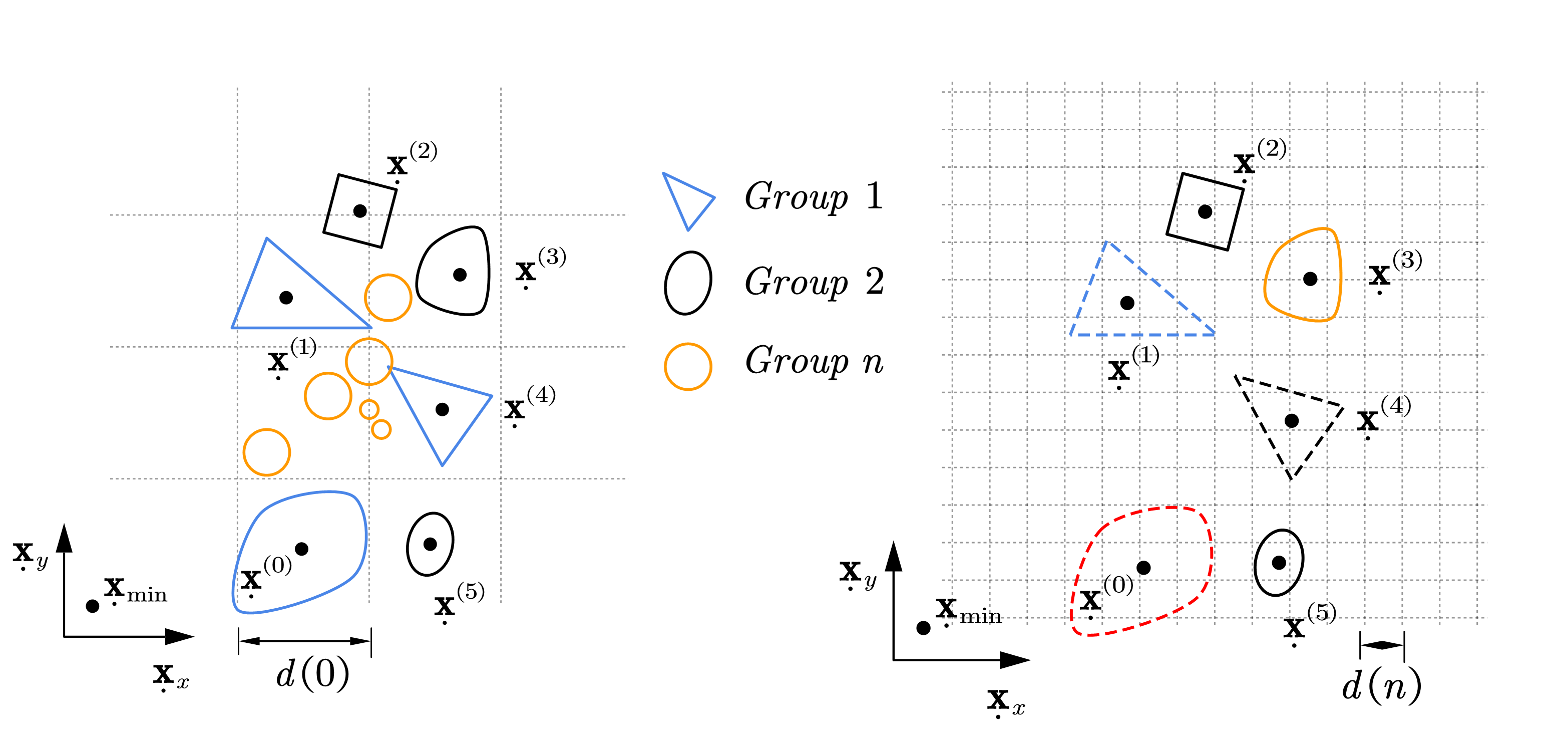
Figure 1. The schematic algorithm of NBS contact detection in OpenFDEM.#
The enhanced NBS contact detection method used in mGbCDM
Step |
Description |
Step 1 |
Loop the blocks and find the maximum size buffer box for the initial group box \(d(0)=d_{\max}\). |
Step 2 |
Divide the blocks into \(n\) groups with size of buffer box for the nth group box as
\[d(n)=d_{\max}\cdot\alpha^{n-1}\]
where \(\alpha\in(0,1]\). |
Step 3 |
All the blocks are mapped into the grid space with edge length of \(d(0)\) as depicted in Figure 2. |
Step 4 |
Loop all the blocks and detect contacts for the first group. The contact couple groups are identified when
\[\left|
\dot{\mathbf{x}}^{(t)}
-
\dot{\mathbf{x}}^{(c)}
\right|
<
\max(d^{(t)}+d^{(c)})\]
|
Step 5 |
Repeat Step 3 and Step 4 for all groups of the remaining blocks. |
Contact force in high-order elements#
Within the quadratic FDEM framework, the contact module of linear FDEM is preserved by simplifying the computation of the overlap area between the contactor and the target. Contact forces are formulated within an energy-based contact model, in which the interaction forces are derived from the derivatives of a conservative interaction potential. The contact force implemented on the contactor is computed through Munjiza’s potential contact theory (Munjiza 2004), given by
where \(\beta _c\) and \(\beta _t\) are the zones of the contactor and target elements respectively, \(\varphi _c\) and \(\varphi _t\) are the contact potential functions, and \(p_c\) is the contact penalty stiffness. Notably, the contact potential function \(\varphi\) in a quadratic element is the same as that of a linear element enclosed by the same vertices, given by
where \(A_i\left( i=1,2,3 \right)\) is the area of the sub-triangle enclosed by the node \(x\) and the element’s corresponding edge. The potential vanishes on the element boundary and reaches its maximum value of one at the element center.
Since it is costly to compute the exact overlap zone between two quadratic elements with parabolic edges, a simplified strategy is used that computes the overlap zone by treating the quadratic element as a linear element, as shown in Figure 2 (a). Provided the quadratic elements do not undergo excessive distortion, the introduced deviation is very limited, because the contact penalty stiffness is often very large and the overlap between two contact elements is small.
Based on the Gauss integration law, Eq. 2 can be transformed to an integral over the boundary of the overlap zone, and the contact force can be expressed as an equivalent distributed contact traction \(\boldsymbol{t}_{cont}\)
where the equivalent contact traction is \(\boldsymbol{t}_{cont}=\boldsymbol{n}_{\varGamma}p_c\left( \varphi _c-\varphi _t \right)\), and \(\boldsymbol{n}_{\varGamma}\) is the outward unit normal to the boundary \(\varGamma _{cont}\). Based on the virtual work theory, the equivalent nodal force in the quadratic element can be naturally computed, as shown in Figure 2 (c).
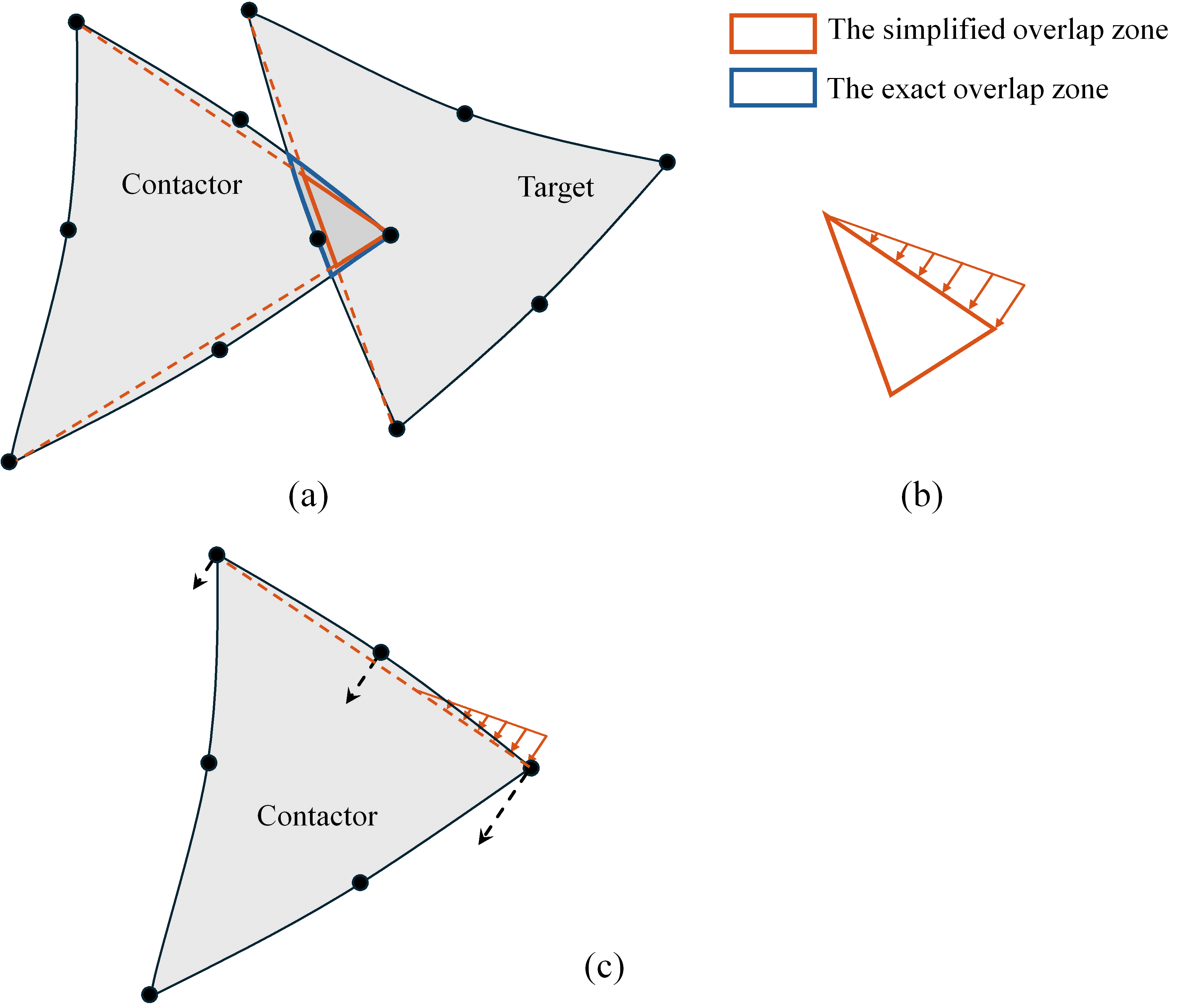
Figure 2. The contact force computation in qFDEM: (a) The simplified overlap zone; (b) The equivalent contact traction distributed on one edge of the overlap; (c) The equivalent nodal force.#
Note that the contact search algorithm in linear FDEM is also applicable to quadratic FDEM, as the mechanical part of the contact module is preserved.