Solid FEM#

In this document, the following conventions are assumed for the notations:

  • Gibbs notation is employed for tensor algebra and the order is denoted by the number of underdots (e.g. \({\mathbf{u}} = u_{i}\mathbf{e}_{\mathbf{i}}\),\({\mathbf{\sigma}} = \sigma_{ij}\mathbf{e}_{\mathbf{i}} \otimes \mathbf{e}_{\mathbf{j}}\));

  • the dot symbol means the contraction between two tensors (e.g. \({\mathbf{T}} = {\mathbf{\sigma}} \cdot {\mathbf{n}}\));

  • the colon symbol denotes for the double contraction of two second-order tensors (e.g. \({\mathbf{\sigma}} = {\mathbf{D}} : {\mathbf{\varepsilon}}\));

  • the wedge symbol \(\land\) is for the cross product (e.g. \(\mathbf{e}_{3} = \mathbf{e}_{1} \land \mathbf{e}_{2}\)) and,

  • the tensorial product \({\mathbf{\sigma}} = {\mathbf{x}} \otimes {\mathbf{F}}\) states for the linear production two tensors.

Weak formulation of updated Lagrange#

Timesteps

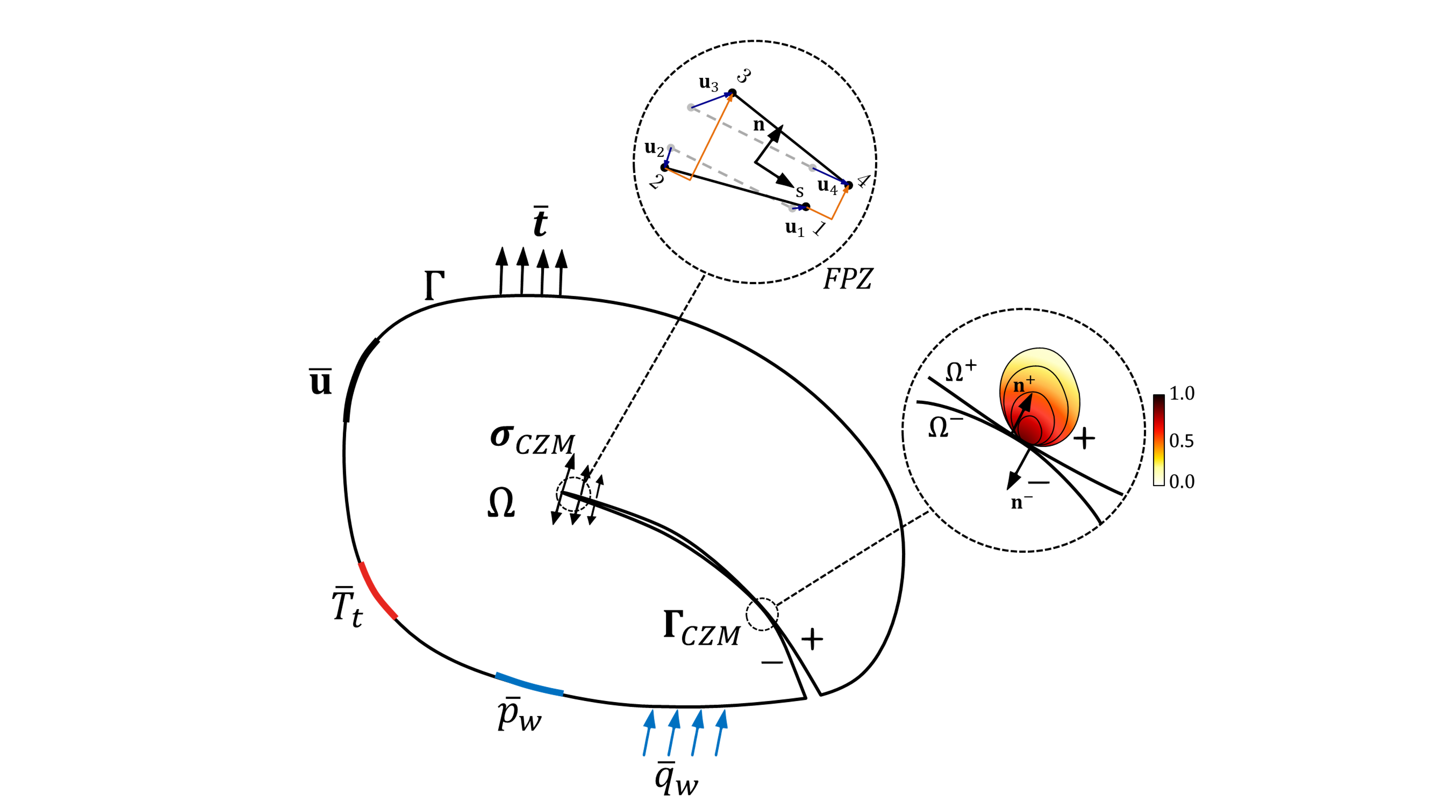
Figure 1: The theory of FDEM body#

Consider an arbitrary body \(\Omega \subset \mathbb{R}^{D}\left( D\ \in \ [\ 1\ ,\ 2\ ,\ 3\ ] \right)\) with external boundary \(\partial\Omega\) and the internal discontinuity boundary \(\Gamma\), \({\mathbf{x}}\) is the current position vector of the point and \({\mathbf{u}}\left( {\mathbf{x}}\ ,t \right) \subset \mathbb{R}^{D}\) is the displacement at time \(t \in \left\lbrack 0\ ,\ t_{all} \right\rbrack\). The infinitesimal strain tensor based on small deformation and deformation gradients assumptions is characterized as \({\mathbf{\varepsilon}}\left( {\mathbf{x}}\ ,\ t \right) \in \mathbb{R}^{D \times D}\).

Balance of mass:

\[\dot{\rho}+\rho \nabla \cdot \mathbf{\dot{u}}=0 \quad \forall{\mathbf{x}} \in \Omega \tag{1}\]

Balance of momentum:

\[\frac{d}{dt}\int_{\Omega}^{}\rho{\dot{\mathbf{u}}}\left( {\mathbf{x}} \right)d\Omega = \int_{\Omega}^{}\rho{\ddot{\mathbf{u}}}\left( {\mathbf{x}} \right)d\Omega = \int_{\partial\Omega}^{}{\mathbf{t}}d\partial\Omega + \int_{\Omega}^{}{\mathbf{b}}d\Omega \tag{2}\]

where \(\rho\) is the density of the solid body. The force is split into tractions \({\mathbf{t}}\) acted on boundaries \(\partial\Omega\) and into body force \({\mathbf{b}}\) in volume \(\Omega \mapsto \mathbb{R}^{D}\). Similarly, the conservation of the moment of momentum can be written as

\[\int_{\Omega}^{}\rho{\ddot{\mathbf{u}}}\left( {\mathbf{x}} \right) \land {\mathbf{x}}d\Omega = \int_{\partial\Omega}^{}{\mathbf{t}} \land {\mathbf{x}}d\partial\Omega + \int_{\Omega}^{}{{\mathbf{b}} \land {\mathbf{x}}}d\Omega \tag{3}\]

In terms of the Cauchy stress tensor, the traction force satisfies \({\mathbf{t}} = {\mathbf{\sigma}} \cdot {\mathbf{n}}\), The equation above is rewritten according to Gausss theorem \(\int_{\partial\Omega}^{}{\mathbf{t}}d\partial\Omega = \int_{\partial\Omega}^{}{{\mathbf{\sigma}} \cdot {\mathbf{n}}}d\partial\Omega = \int_{\Omega}^{}{{\mathbf{\sigma}} \cdot \nabla}d\Omega\). Since the stress tensor is symmetric as \({\mathbf{\sigma}} = {{\mathbf{\sigma}}}^{T}\), the conservation of momentum is

\[\rho{\ddot{\mathbf{u}}}\left( {\mathbf{x}} \right) - \nabla \cdot {\mathbf{\sigma}} - {\mathbf{b}} = 0 \tag{4}\]

Boundary conditions:

\[ \begin{align}\begin{aligned}{\mathbf{\sigma}} \cdot {\mathbf{n}} = {\mathbf{t}} \quad \forall{\mathbf{x}} \in \partial\Omega_{t}\\{\mathbf{u}} = \overline{{\mathbf{u}}} \quad \forall{\mathbf{x}} \in \partial\Omega_{u}\end{aligned}\end{align} \]

Initial conditions:

\[ \begin{align}\begin{aligned}{\mathbf{u}}\left( {\mathbf{x}}\ ,\ t\ = \ 0 \right) = \overline{{\mathbf{u}}}\left( {\mathbf{x}} \right) \quad \forall{\mathbf{x}} \in \partial\Omega_{u}\\\dot{{\mathbf{u}}}\left( {\mathbf{x}}\ ,\ t\ = \ 0 \right) = \overline{\dot{{\mathbf{u}}}}\left( {\mathbf{x}} \right) \quad \forall{\mathbf{x}} \in \partial\Omega_{u}\end{aligned}\end{align} \]

The spatial version of the principle of virtual work states that the body \(\Omega\) is in equilibrium when the Cauchy stress satisfies the initial condition

\[\int_{\Omega}^{}{\left( \left( \nabla\ \cdot \ {\mathbf{\sigma}} \right)\ \cdot \ \delta\ {\mathbf{v}}\ - \ \left( {\mathbf{b}}\ - \ \rho\ {\ddot{\mathbf{u}}} \right)\ \cdot \ \delta\ {\mathbf{v}} \right)d\Omega} = 0 \tag{5}\]

Integration by parts of the first term gives

\[\int_{\Omega}{\left( \nabla \cdot \mathbf{\sigma } \right)}\cdot \delta \mathbf{v}\mathrm{d}\Omega =\int_{\Omega}{\left( \mathbf{\sigma }\nabla \delta \mathbf{v} \right)}\mathrm{d}\Omega -\int_{\partial \Omega}{\left( \mathbf{\sigma }^{\mathrm{T}}\delta \mathbf{v}\cdot \mathbf{n} \right)}\mathrm{d}\partial \Omega \tag{6}\]

Eq. 6 is changed to

\[\int_{\Omega}{\left( \nabla \cdot \mathbf{\sigma } \right)}\cdot \delta \mathbf{v}\mathrm{d}\Omega =\int_{\Omega}{\left( \mathbf{\sigma }\nabla \delta \mathbf{v} \right)}d\Omega -\int_{\partial \Omega _t}{\left( \mathbf{t}\cdot \delta \mathbf{v} \right)}\mathrm{d}\partial \Omega \tag{7}\]

Substitution of Eq.7 back into Eq.5 gives

\[\int_{\Omega}^{}{\left( {\mathbf{\sigma}}\ : \ \nabla\ \delta\ {\mathbf{v}}\ - \ \left( {\mathbf{b}}\ - \ \rho\ {\ddot{\mathbf{u}}} \right)\ \cdot \ \delta\ {\mathbf{v}} \right)d\Omega = \int_{\partial\Omega_{t}}^{}{{\mathbf{t}} \cdot}}\delta{\mathbf{v}}d\partial\Omega \tag{8}\]

Spatial discretization in finite domain#

In this section, Eq.8 is discretised to derive the mass matrix, internal force and external force which is convenient to the matrix notation. Let the generic finite element \(e \in \Omega\) is defined by \(n_{node}\) nodes with shape function \(\mathcal{N}^{(e)}\left( {\mathbf{x}} \right)\) associated with node \(i\) having coordinate \({\mathbf{x}}\). The global interpolation matrix is defined as

\[\mathcal{N}^{g}\left( {\mathbf{x}} \right) = \left\lbrack diag\ \left\lbrack \mathcal{N}_{1}^{g}\ \left( {\mathbf{x}} \right) \right\rbrack\ \ diag\ \left\lbrack \mathcal{N}_{2}^{g}\ \left( {\mathbf{x}} \right) \right\rbrack\ \cdots\ \ diag\ \left\lbrack \mathcal{N}_{n_{poin}}^{g}\ \left( {\mathbf{x}} \right) \right\rbrack \right\rbrack \tag{9}\]

where \(diag\left\lbrack \mathcal{N}_{1}^{g}\ \left( {\mathbf{x}} \right) \right\rbrack\) is the \(n_{\dim}\)×\(n_{\dim}\) diagonal matrix. The element displacement in global coordinate is

\[{}^{h}{\mathbf{u}}\left( {\mathbf{x}} \right) = \sum_{i = 1}^{n_{poi}}{\mathcal{N}_{i}\left( {\mathbf{x}} \right)}{\mathbf{u}} = \mathcal{N}^{g}{\mathbf{u}} \tag{10}\]
\[\begin{split}\mathcal{B}^{g} = \begin{bmatrix} \mathcal{N}_{1,1}^{g} & 0 & \mathcal{N}_{2,1}^{g} & 0 & \cdots & \mathcal{N}_{n_{poin},1}^{g} & 0 \\ 0 & \mathcal{N}_{1,2}^{g} & 0 & \mathcal{N}_{2,2}^{g} & \cdots & 0 & \mathcal{N}_{n_{poin},2}^{g} \\ \mathcal{N}_{1,2}^{g} & \mathcal{N}_{1,1}^{g} & \mathcal{N}_{2,2}^{g} & \mathcal{N}_{2,1}^{g} & \cdots & \mathcal{N}_{n_{poin},2}^{g} & \mathcal{N}_{n_{poin},1}^{g} \end{bmatrix}\end{split}\]

Therefore, the discretised virtual work expression considering the kinetic is

\[\int_{{}^{h}\Omega}^{}\left\lbrack {{\mathbf{\sigma}}}^{T}\ \mathcal{B}^{g}\ \delta\ {\mathbf{v}}\ - \ \left( {\mathbf{b}}\ - \ \rho\ {\ddot{\mathbf{u}}} \right)\ \cdot \ \mathcal{N}^{g}\ \delta\ {\mathbf{v}} \right\rbrack d\Omega - \int_{\partial^{h}\Omega_{t}}^{}{\mathbf{t}} \cdot \mathcal{N}^{g}\delta{\mathbf{v}}d\partial\Omega = 0 \tag{11}\]

Since the above equation is satisfied for all vectors \(\delta{\mathbf{v}}\), Eq. 10 can be reformulated as

\[\mathbf{M}^{FE}{\ddot{\mathbf{u}}} + {{\mathbf{f}}}^{int}\left( {\mathbf{u}} \right) - {{\mathbf{f}}}^{ext} = 0 \tag{12}\]

while the internal force \({{\mathbf{f}}}^{int}\left( {\mathbf{u}} \right)\), external force \({{\mathbf{f}}}^{ext}\)and inertia mass \(\mathbf{M}^{FE}\) are

\[{{\mathbf{f}}}^{int}\left( {\mathbf{u}} \right) = \int_{{}^{h}\Omega}^{}{\left( \mathcal{B}^{g} \right)^{T} \cdot {\mathbf{\sigma}}\left( {\mathbf{u}} \right)d\Omega} \tag{13}\]
\[{{\mathbf{f}}}^{ext} = \int_{{}^{h}\Omega}^{}{\left( \mathcal{N}^{g} \right)^{T}\rho{\mathbf{b}}d\Omega} + \int_{\partial^{h}\Omega_{t}}^{}{\left( \mathcal{N}^{g} \right)^{T}{\mathbf{t}}}d\partial\Omega = 0 \tag{14}\]
\[\mathbf{M}^{FE} = \int_{{}^{h}\Omega}^{}{\left( \mathcal{N}^{g} \right)^{T}\rho\mathcal{N}^{g}d\Omega} \tag{15}\]

\(\mathcal{B}^{g}\) and \(\mathcal{N}^{g}\) are matrices incorporating the interpolation functions and their spatial derivatives in global, respectively. The actual force vectors are assembled as

\[{{\mathbf{f}}}^{int} = \overset{e = 1}{\underset{n_{elem}}{\mathbf{A}}}\left( {{\mathbf{f}}}_{(e)}^{int} \right) \tag{16}\]
\[{{\mathbf{f}}}^{ext} = \overset{e = 1}{\underset{n_{elem}}{\mathbf{A}}}\left( {{\mathbf{f}}}_{(e)}^{ext} \right) \tag{17}\]

where \(\overset{e = 1}{\underset{n_{elem}}{\mathbf{A}}}\) is the finite element assembly operator and the element force vector can be obtained as

\[{{\mathbf{f}}}_{(e)}^{int}\left( {\mathbf{u}} \right) = \int_{{}^{e}\Omega}^{}{\left( \mathcal{B}^{e} \right)^{T} \cdot {\mathbf{\sigma}}\left( {\mathbf{u}} \right)d\Omega} \tag{18}\]
\[{{\mathbf{f}}}_{(e)}^{ext} = \int_{{}^{e}\Omega}^{}{\left( \mathcal{N}^{e} \right)^{T}\rho{\mathbf{b}}d\Omega} + \int_{\partial^{e}\Omega_{t}}^{}{\left( \mathcal{N}^{e} \right)^{T}{\mathbf{t}}}d\partial\Omega = 0 \tag{19}\]

The superscripts \(e\) denotes the variables in local element.

Dynamic relaxation and time integration scheme#

The continuum-discontinuum method (CDM) employs the explicit time integration based on velocity verlet algorithm to solve Eq .12, \({}^{n + 1}\dot{{\mathbf{u}}}\) and \({}^{n}{\mathbf{u}}\) are the velocity vector and displacement vector at \({}^{n + 1}t\) and \({}^{n}t\) for a time step \(\mathrm{\Delta}t\)

\[{}^{n}\ddot{{\mathbf{u}}} = \frac{1}{2\mathrm{\Delta}t}\left( {}^{n + 1}\ \dot{{\mathbf{u}}}\ -^{n}\ \dot{{\mathbf{u}}} \right) \tag{20}\]
\[{}^{n}\dot{{\mathbf{u}}} =^{n + 1}{\mathbf{u}} -^{n}{\mathbf{u}} \tag{21}\]

If the damping matrix \(\mathbf{C}^{FE} = \alpha\mathbf{M}^{FE}\) is considered, the governing equation is written as

\[\mathbf{M}^{FE}{\ddot{\mathbf{u}}} + \mathbf{C}^{FE}\dot{{\mathbf{u}}} + {{\mathbf{f}}}^{int}\left( {\mathbf{u}} \right) - {{\mathbf{f}}}^{ext} = 0 \tag{22}\]

Eq. can be rewritten in the form of nodal velocities

\[^{\mathrm{n}+1}\mathbf{\dot{u}}=\left[ \left( 1-2\alpha \Delta t \right) ^{\mathrm{n}}\mathbf{\dot{u}}+\frac{2\Delta t}{\mathbf{M}}\left( ^{\mathrm{n}}\mathbf{f}^{ext}-^{\mathrm{n}}\mathbf{f}^{int}\left( ^{\mathrm{n}}\mathbf{u} \right) \right) \right] \tag{23}\]

while the damping coefficient is \(\alpha = 2\xi\omega\), \(\xi\) is the damping ratio and \(\omega\) is the frequency parameter. The stability of the explicit scheme is depended on the critical timestep, which is determined by

\[\mathrm{\Delta}t_{cri} = \gamma\frac{2}{\omega}\left( \sqrt{\xi^{2} + 1}\ - \ \xi \right) \tag{24}\]

In CDM, each triangular element is considered as elastic with constant strain. During each timestep, the element strain rate is computed as

\[\dot{{\mathbf{\varepsilon}}} = \frac{1}{2}\left( \nabla\ \dot{{\mathbf{u}}}\ + \ \nabla^{T}\ \dot{{\mathbf{u}}} \right),\dot{{\mathbf{\theta}}} = \frac{1}{2}\left( \nabla\ \dot{{\mathbf{u}}}\ - \ \nabla^{T}\ \dot{{\mathbf{u}}} \right),\nabla\dot{{\mathbf{u}}} \cong \frac{1}{2A}\sum_{s}^{}{\left( {\dot{{\mathbf{u}}}}^{(a)}\ + \ {\dot{{\mathbf{u}}}}^{(b)} \right) \cdot \mathbf{n}\mathrm{\Delta}s} \tag{25}\]

The incremental strain tensor is denoted as \(\mathrm{\Delta}\varepsilon_{ij} = {\dot{\varepsilon}}_{ij}\mathrm{\Delta}t\), \(\mathbf{n}\) is unit vector in normal direction, \(A\) is the area and \(s\) is the length of edge, the incremental stress is updated according to the constitutive relations of the isotropic elastic blocks as

\[\mathrm{\Delta}{\mathbf{\sigma}} = \lambda{\dot{{\mathbf{\varepsilon}}}}_{v}\mathbf{\delta}\mathrm{\Delta}t + 2\mu\dot{{\mathbf{e}}}\mathrm{\Delta}t \tag{26}\]

where \(\mathbf{\delta}\) is Kronecker symbol, \(\lambda\) and \(G\) are Lame constants. The updated stress and strain at \(n\) step are

\[{}^{n + 1}{\mathbf{\sigma}} =^{n}{\mathbf{\sigma}} + \mathrm{\Delta}{\mathbf{\sigma}},{}^{n + 1}\dot{{\mathbf{\varepsilon}}} =^{n}\dot{{\mathbf{\varepsilon}}} + \mathrm{\Delta}{\mathbf{\varepsilon}} \tag{27}\]

High-order bulk element#

The classical FDEM framework is limited to linear elements, as both its cohesive element formulation and contact algorithm rely on the linear-edge assumption. OpenFDEM generalizes it to an arbitrary higher-order element framework. For simplicity, the quadratic triangular element is used as a primary example here; the shape functions of other higher-order elements can be constructed similarly.

The shape functions serve as a fundamental mathematical basis for interpolating field variables within a bulk element from nodal values. Shape functions of arbitrary order of triangular and rectangular elements can be constructed through approaches based on the barycentric coordinates method and the Lagrange polynomials method.

For a triangular element of arbitrary order \(p\), the shape functions have a universal form as

\[N_{rst}\left( \lambda _1,\lambda _2,\lambda _3 \right) =\frac{p!}{r!s!t!}\lambda _{1}^{r}\lambda _{2}^{s}\lambda _{3}^{t},\quad r+s+t=p \tag{28}\]

where \(\lambda _1, \lambda _2, \lambda _3\) are the area coordinates of the corresponding node, which satisfy

\[\lambda _i(\xi ,\eta )=\frac{1}{2A}\left[ \left( \xi _j-\xi \right) \left( \eta _k-\eta \right) -\left( \xi _k-\xi \right) \left( \eta _j-\eta \right) \right] \tag{29}\]
\[\lambda _1=\frac{r}{p},\quad \lambda _2=\frac{s}{p},\quad \lambda _3=\frac{t}{p} \tag{30}\]

where \(A\) is the area of the triangle. Using Eq. 30, values of \(r, s, t\) in Eq. 28 can be obtained naturally.

For a quadrilateral element of arbitrary order \(p\), the shape functions can be expressed as

\[N_{ij}(\xi ,\eta )=l_i(\xi )\cdot l_j(\eta ) \tag{31}\]

where \(l_i(\xi )\) and \(l_j(\eta )\) are the one-dimensional Lagrange polynomials in natural coordinates \((\xi ,\eta )\), given by

\[l_i(\xi )=\prod_{\substack{m=0\\m\ne i}}^p{\frac{\xi -\xi _m}{\xi _i-\xi _m}},\quad \xi _m\in [-1,1] \tag{32}\]
\[l_j(\eta )=\prod_{\substack{m=0\\m\ne j}}^p{\frac{\eta -\eta _m}{\eta _j-\eta _m}},\quad \eta _m\in [-1,1] \tag{33}\]
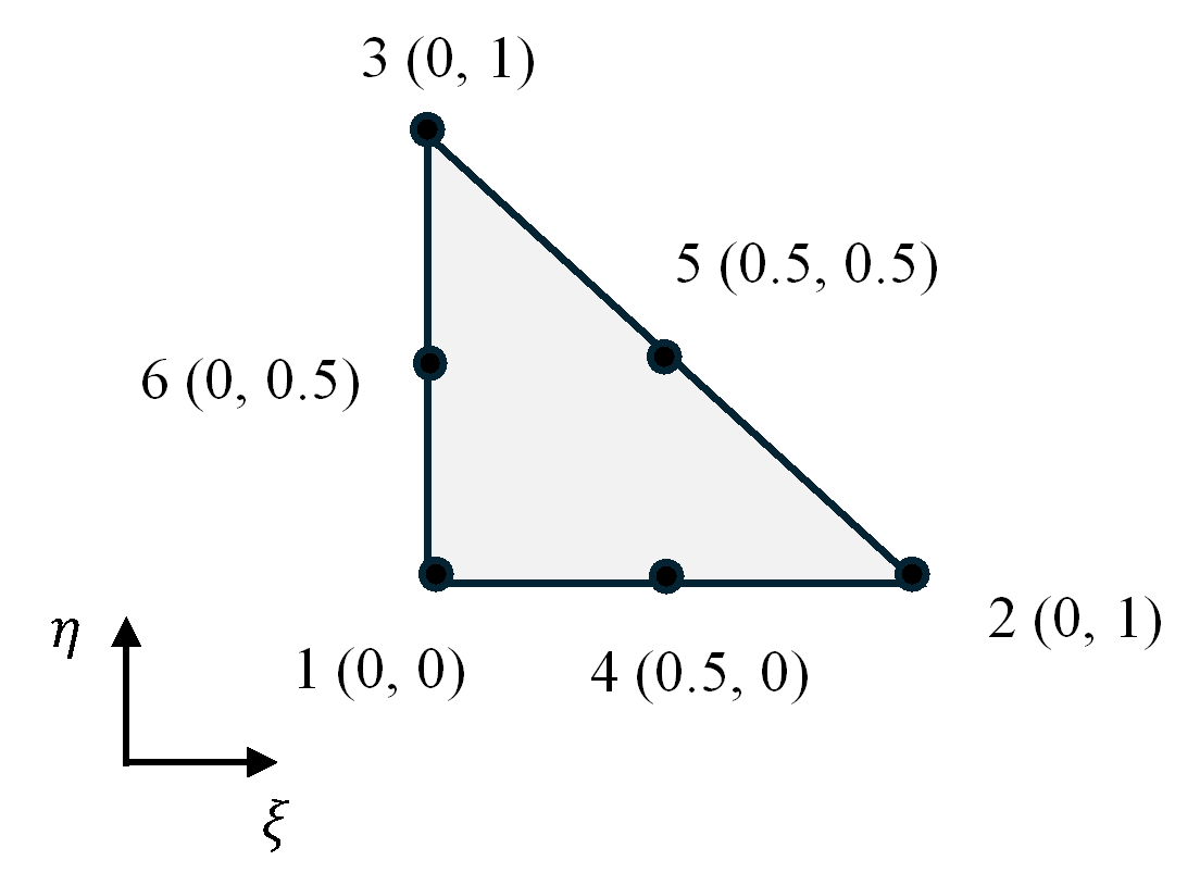
Quadratic triangle element in natural coordinates

Figure 2. Quadratic triangle element in natural coordinates.#

In detail, using Eq. 28, the shape functions of the quadratic triangle element are obtained as

\[\begin{aligned} N_1\left( \xi ,\eta \right) &=-\left( 1-\xi -\eta \right) \left( 1-2\left( 1-\xi -\eta \right) \right) \\ N_2\left( \xi ,\eta \right) &=-\xi \left( 1-2\xi \right) \\ N_3\left( \xi ,\eta \right) &=-\eta \left( 1-2\eta \right) \\ N_4\left( \xi ,\eta \right) &=4\xi \left( 1-\xi -\eta \right) \\ N_5\left( \xi ,\eta \right) &=4\xi \eta \\ N_6\left( \xi ,\eta \right) &=4\eta \left( 1-\xi -\eta \right) \end{aligned} \tag{34}\]

where the subscript denotes the corresponding nodes shown in Figure 2. It is simple to employ quadratic order shape functions to compute the internal nodal force of the bulk element (Eq. 18) and the nodal external force (Eq. 19), in the same way used in the finite element method. The strain matrix \(\mathcal{B}\) of quadratic order in natural coordinates can also be derived accordingly.