Phase Field#
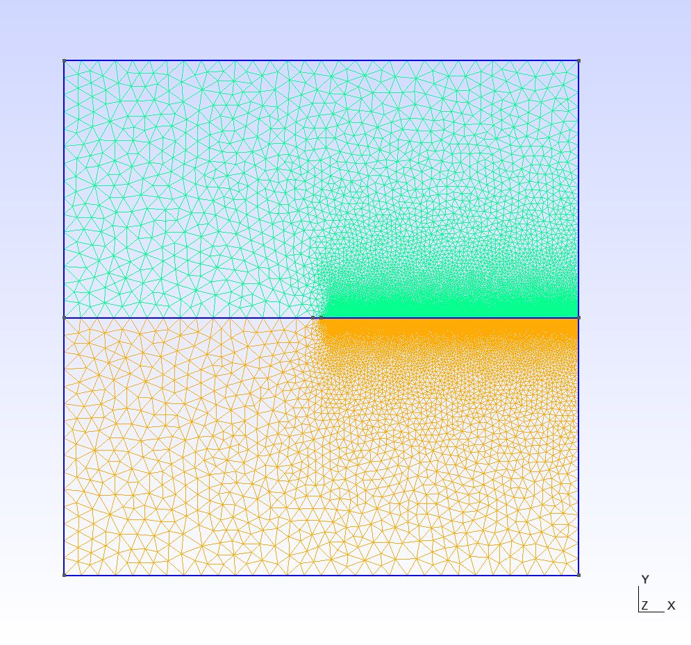
Figure 1: Geometry of the uniaxial compression strength test#
1 Main Steps#
Initialize the model.
Create the geometry and the mesh
Assign material properties.
Create the group and assign boundary conditions.
Set the outputs.
2 Codes#
Please note that, all the setting in the example is based on the developer’s computer. You may need to change these setting based on your own conditions.
To start with programming, create a new empty text file (later add the .of extension). Begin writing the following commands:
2.1 Initialize the model#
Create a new run and clean up the old memories.
of.new
Set up the folder name to save your results. Here the folder name is set to be “result”.
of.set.result "result"
Turn off the contact module, no contacts will be considered in this simulation.
of.set.contact off
Set the minangle to delete the bad segments for joints and DFNs.
of.geometry.minangle 0.0
Set the number of cores to be used for running this model.
of.set.omp 15
2.2 Create the geometry and the mesh#
See Figur 1 to create a polygon with 9 points.
of.geometry.polygon 'plate' size 9
[-30e-3 30e-3]
[-30e-3 0.01e-3]
[-1e-3 0.01e-3]
[-0e-3 0.0]
[-1e-3 -0.01e-3]
[-30e-3 -0.01e-3]
[-30e-3 -30e-3]
[30e-3 -30e-3]
[30e-3 30e-3]
Cut the joints in the plate.
of.geometry.cut.joint 'Line' 'plate' [-12e-3 0 30e-3 0.0]
Group the geometries.
of.geometry.nodal.group 'tip_Zone' range box.in [0e-3 1e-3 -0.050e-3  0.050e-3 ]
of.geometry.nodal.group 'cohesive_Zone' range box.in [9e-3 11e-3 -30e-3  30e-3]
Set different mesh size for different group of geometries.
of.geometry.mesh.size 'default' 2.0e-3
of.geometry.mesh.size 'Line' 0.05e-3
of.geometry.mesh.size 'cohesive_Zone' 0.1e-3
of.geometry.mesh.size 'tip_Zone' 0.05e-3
Create the mesh.
of.geometry.mesh delaunay
Group the elements in a mesh.
of.group.element 'Mat2' range plane.below x0 10e-3 y0 -40e-3 x1 10e-3 y1 40e-3
2.3 Assign Material and Thermal Properties#
Set the material properties.
of.mat.element 'plate' elastic den 2700 E 30e9 v 0.3 lc 1.0e-4 Gc 200 nita 1 damp 0.0
of.mat.element 'Mat2' elastic den 2700 E 20e9 v 0.3 lc 1.0e-4 Gc 100 nita 1 damp 0.0
Assign materials contacts.
of.mat.contact 'default' MC fric 0.3
2.4 Create Groups and Assign Boundary Conditions#
Group the nodes to prepare for the next step.
of.group.edge 'up_b' range plane.on x0 -30e-3 y0 30e-3 x1 30e-3 y1 30e-3
of.group.edge 'bottow_b' range plane.on x0 -30e-3 y0 -30e-3 x1 30e-3 y1 -30e-3
Assign the pressure boundary conditions.
of.boundary.edge.pressure 'up_b' normal -1 ntable stress
of.boundary.edge.pressure 'bottow_b' normal -1 ntable stress
2.5 Set the Outputs#
Set the output interval to be every 2000 steps and output all fields variables and fracture variables. Control the output interval to a reasonable size could shorten the computation time but get a good understanding of the model.
of.history.pv.interval 2000
of.history.pv.field default
The program will run 100000 steps in total. In other words, it will output 10 files for reference.
of.step 100000
Finalize the model and clear all the temporary memories.
of.finalize
Save the notepad and double click the .of file to run the program.
3 Run the Program#
When you run the program, you can first check the mesh that was created by Gmsh as shown in Figure 2. If the mesh has a good quality, you can close the window to continue run the program.
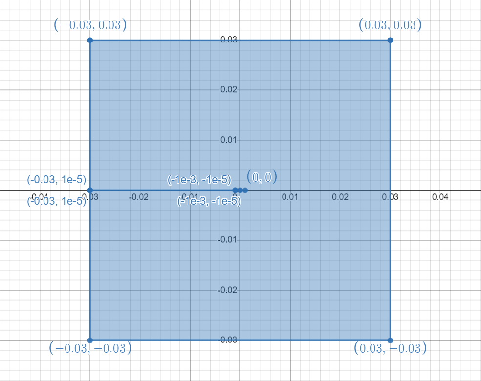
Figure 2: Mesh created by Gmsh#
The phase field module is ON in this model.
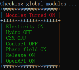
Figure 3: Global modules#
Material properties you set on step 2.3 will be shown on the screen. You can confirm it while the program just starts to run.
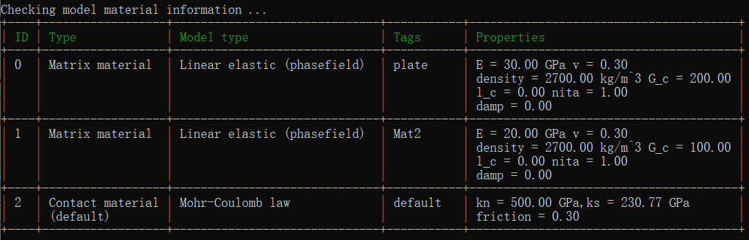
Figure 4: Check the material assignment from command window#
4 Results#
Wait for updates.
5 Full Script#
Phase_Field.of (click to download from GitHub)
# initialization, this command is to clear the memory in your last run, it is not
# mandatory but strongly recommend.
of.new

# Set the path folder of your output results, //result// in the same path of your input
# file will be created by default
of.set.result "result"

# turn off the contact
of.set.contact off

# Set the minangle to delete the bad segments for jsets and dfns.
of.geometry.minangle 0.0

# Set the number of cores you want to use, the parallization will be automatically
# turned on when you use the following command, otherwise the serilization will be used
# by default
of.set.omp 15

##################################### create mesh #######################################
of.geometry.polygon 'plate' size 9
[-30e-3 30e-3]
[-30e-3 0.01e-3]
[-1e-3 0.01e-3]
[-0e-3 0.0]
[-1e-3 -0.01e-3]
[-30e-3 -0.01e-3]
[-30e-3 -30e-3]
[30e-3 -30e-3]
[30e-3 30e-3]

# Cut the joints in the plate.
of.geometry.cut.joint 'Line' 'plate' [-12e-3 0 30e-3 0.0]

of.geometry.nodal.group 'tip_Zone' range box.in [0e-3 1e-3 -0.050e-3  0.050e-3 ]
of.geometry.nodal.group 'cohesive_Zone' range box.in [9e-3 11e-3 -30e-3  30e-3]

of.geometry.mesh.size 'default' 2.0e-3
of.geometry.mesh.size 'Line' 0.05e-3
of.geometry.mesh.size 'cohesive_Zone' 0.1e-3
of.geometry.mesh.size 'tip_Zone' 0.05e-3

of.geometry.mesh delaunay

of.group.element 'Mat2' range plane.below x0 10e-3 y0 -40e-3 x1 10e-3 y1 40e-3

################################ assign material parameters #############################
# assign material for matrix
of.mat.element 'plate' elastic den 2700 E 30e9 v 0.3 lc 1.0e-4 Gc 200 nita 1 damp 0.0
of.mat.element 'Mat2' elastic den 2700 E 20e9 v 0.3 lc 1.0e-4 Gc 100 nita 1 damp 0.0
# assign materials for contacts
of.mat.contact 'default' MC fric 0.3

#################################### create groups ######################################
of.group.edge 'up_b' range plane.on x0 -30e-3 y0 30e-3 x1 30e-3 y1 30e-3
of.group.edge 'bottow_b' range plane.on x0 -30e-3 y0 -30e-3 x1 30e-3 y1 -30e-3

################################### assign boundaries ###################################
# import the data table
of.import.table stress 'load.dat'

# Assign the boundary conditions
of.boundary.edge.pressure 'up_b' normal -1 ntable stress
of.boundary.edge.pressure 'bottow_b' normal -1 ntable stress

###################################### set output #######################################
# Set the interval of writing ParaView results.
of.history.pv.interval 2000
of.history.pv.field default

##################################### execute model #####################################
# to excuate the model
of.step 100000
# finalize the model and clear the memory
of.finalize