Quick start with Brazilian disc test#
Brazilian Disc Test is a geotechnical laboratory test for indirect measurement of tensile strength of rocks. Due to its simplicity and efficiencly, it is amonst the most commonly used laboratory testing methods in geotechnical investigation in rocks. It is also used as a benchmark test for calibrating the tensile behaviour of rocks in FDEM.
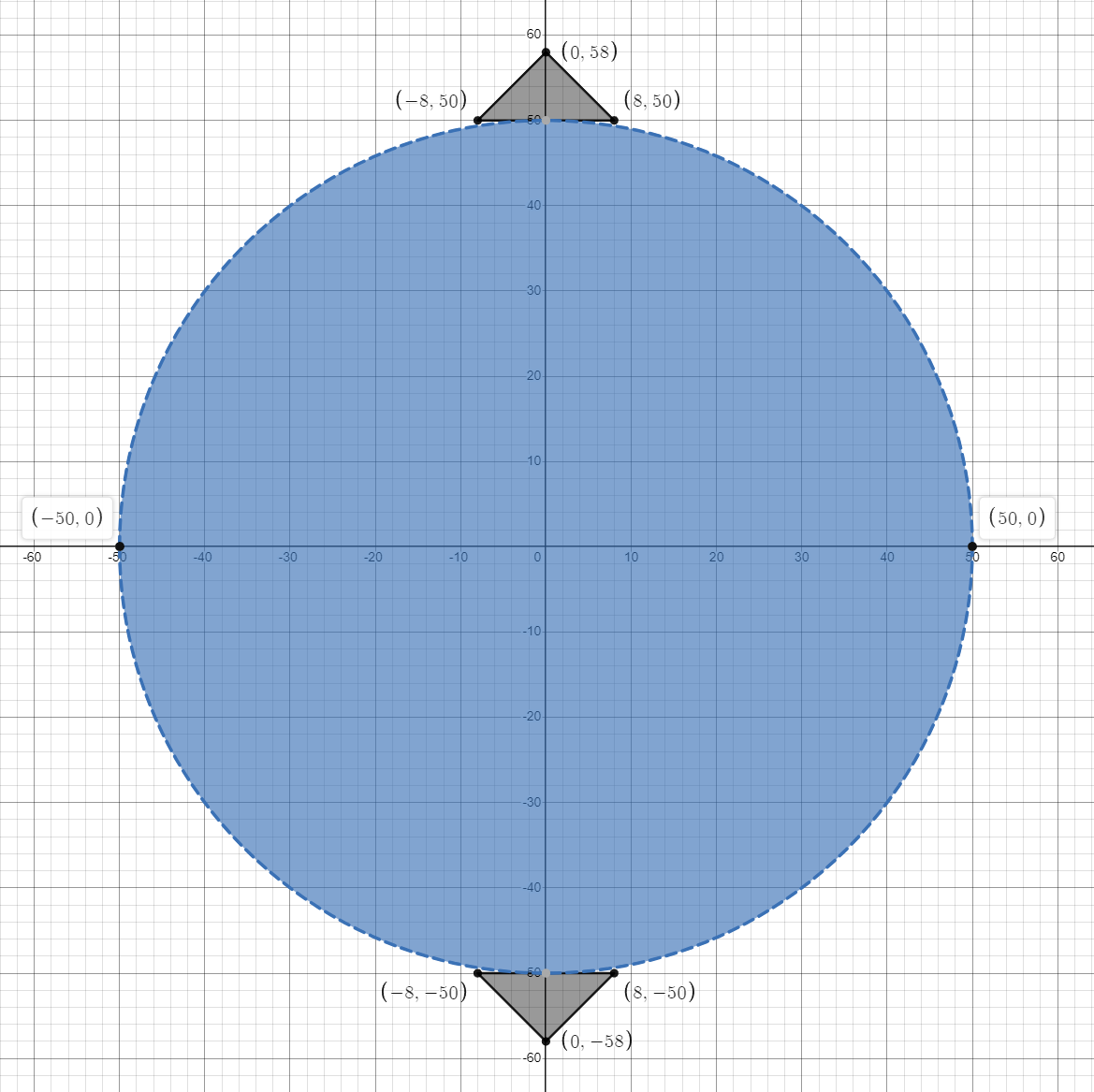
Figure 1: Geometry of the Brazilian disc test#
1 Tutorial Prerequistes#
The following files are needed to follow along the tutorial:
example_br.geo (click to download from GitHub)
2 Main Steps#
Initialize the model.
Import the geometry and the mesh
Assign material properties.
Create the group
Assign boundary conditions.
Set the outputs.
Run.
3 Codes#
Warning
Please note that, all the setting in the example is based on the developer’s computer. You may need to change these details based on your own environment.
To start with runing, create a new empty text file (later add the .of extension). Begin writing the following commands:
3.1 Initialize the model#
Create a new run and clean up the dirty memories in heap, it is not mandatory but strongly recommended.
of.new
Set up the path to save your results. Here the folder is set to be “result”.
of.set.result "result"
Set the number of cores to be used for running this model.
Warning
In the default example, 15 cores will be used for running. To prevent the heavy burden of your computer, please check your computer to change core number you want to use. To check the configuration of your computer, you can go
- Windows:
Task Manager > Performance > CPU > Cores
- Linux:
lscpu
lscpu | egrep ‘Model name|Socket|Thread|NUMA|CPU(s)’
lscpu -p
The cores will be printed on the console when you start a new run, you can also check the information from OpenFDEM kernel itself.
of.set.omp 15
3.2 Import the geometry and the mesh#
Import the geometry and mesh of the model from the “example_br.geo” file. The final geometry will be the same as Figure 1 shown.
of.import 'example_br.geo'
Group the elements to rock, top platen and bottom platen.
of.group.element 'rock' range box.in xmin -50.0 xmax 50.0 ymin -50.0 ymax 50.0
of.group.element 'up' range box.in xmin -500.0 xmax 500.0 ymin 50.0 ymax 100.0
of.group.element 'down' range box.in xmin -500.0 xmax 500.0 ymin -500.0 ymax -50.0
Insert the cohesive elements to the mesh.
of.mesh.insert 'rock'
3.3 Assign Material Properties#
The material properties of this model is shown as the table below:
Parameter |
Value |
|---|---|
Continuum Triangular Elements - Rock |
|
model |
elastic |
density (\(kg/m^3\)) |
2700 |
E (Pa) |
30e9 |
\(\nu\) |
0.3 |
damp |
0.6 |
Continuum Triangular Elements - Platens |
|
model |
rigid |
density (\(kg/m^3\)) |
7000 |
Cohesive Material Properties |
|
model |
EM |
tension (Pa) |
1e6 |
cohesion (Pa) |
3e6 |
friction |
0.3 |
GI (\(J/m^2\)) |
10 |
GII (\(J/m^2\)) |
50 |
Contact Material Properties |
|
model |
MC |
friction |
0.3 |
Note
Check element materal, cohesive materal, contact materal to see more materials.
Set the material properties. elastic material is assigned for the matrix element and Evans_Marathe cohesive law is for CZM, the contact uses Mohr-Coulomb slip by default.
of.mat.element 'rock' elastic den 2700 E 30e9 v 0.3 damp 0.6
of.mat.element 'up' rigid den 7000
of.mat.element 'down' rigid den 7000
of.mat.cohesive 'default' EM ten 1e6 coh 3e6 fric 0.3 GI 10 GII 50
of.mat.contact 'default' MC fric 0.3
3.4 Create Groups and Assign Boundary Conditions#
Group the nodes to prepare for the next step.
Note
- There are three methods to group nodals in the mesh.
box.in/box.on/box.out x [x_min x_max] y [y_min y_max] or [x_min x_max y_min y_max]
circle.in/circle.on/circle.out center [x y] radius rad or [x y radius]
plane.on/plane.above/plane.below p0 [x0 y0] p1 [x1 y1] or [x0 y0 x1 y1]
of.group.nodal 'up' range box.in xmin -100.0 xmax 100.0 ymin 50.0 ymax 500.0
of.group.nodal 'down' range box.in xmin -100.0 xmax 100.0 ymin -500.0 ymax -50.0
Assign the nodal boundaries. In this example, platens are fixed in the x direction and moving with 0.005 m/s in y direction.
of.boundary.nodal.velocity  'up' x 0.0 y -0.005
of.boundary.nodal.velocity  'down' x 0.0 y 0.005
3.5 Set the Outputs#
Set the output interval to be every 2000 steps and output all fields variables and fracture variables.
of.history.pv.interval 2000
of.history.pv.field default
of.history.pv.fracture default
3.6 Run#
The program will run 500000 steps to terminate the model.
of.step 500000
Finalize the model and clear all the temporary memories.
of.finalize
Save the notepad and double click the
.offile to run the program.
4 Run the Program#
When you run the program, you can first check the mesh that was created by Gmsh as shown in Figure 2. If the mesh has a good quality, you can close the window to continue run the program.
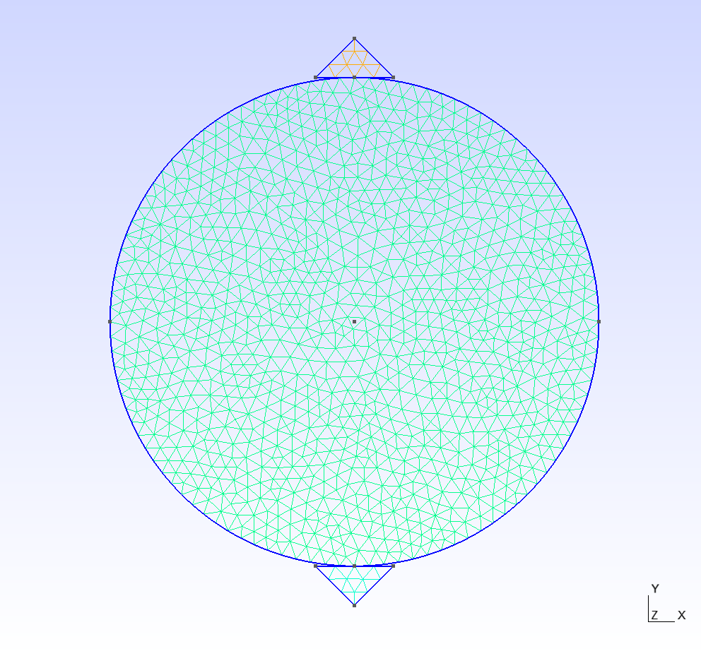
Figure 2: Mesh created by Gmsh#
5 Results#
X Displacement
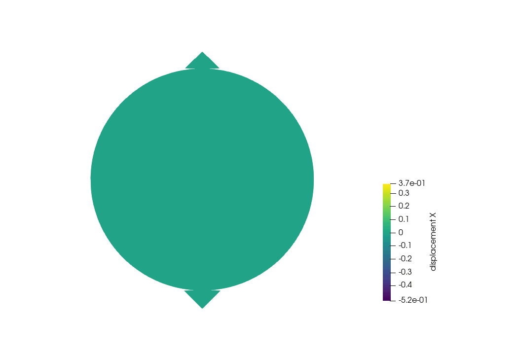
Figure 3: BD Stress XX#
Stress XX
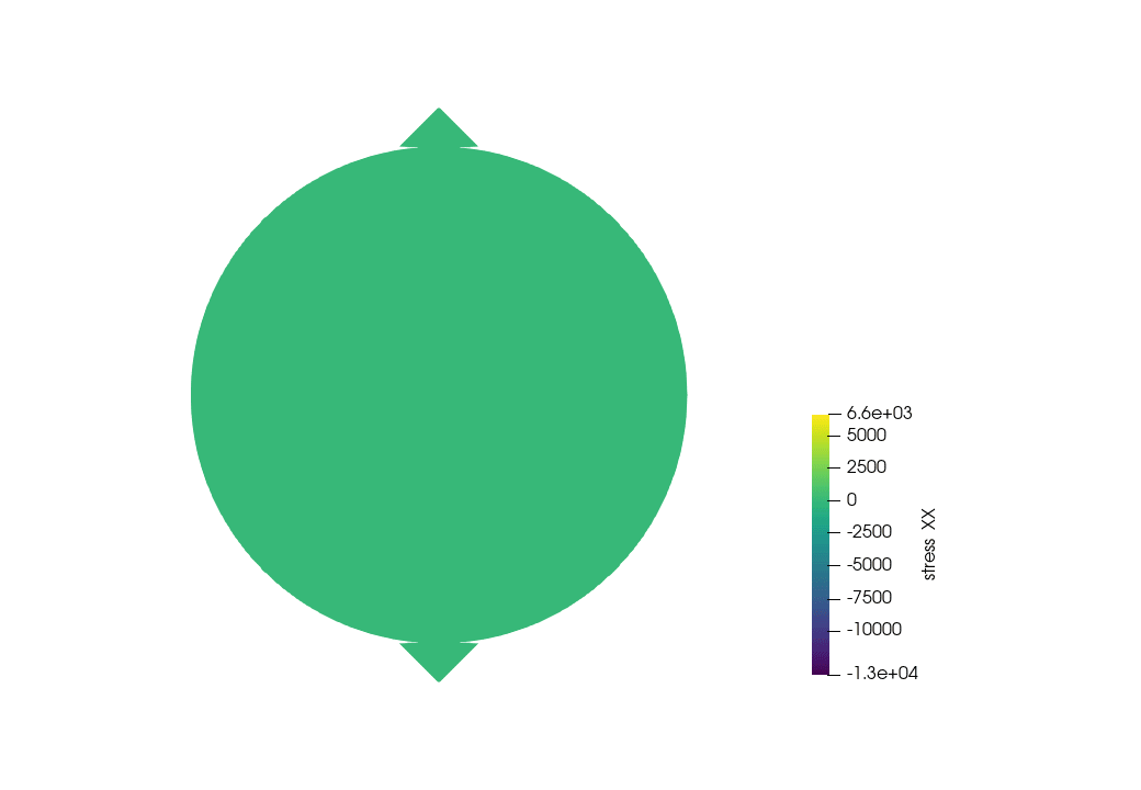
Figure 4: BD Stress YY#
6 Full Script#
BD_test.of (click to download from GitHub gist)
# initialization, this command is to clear the memory in your last run, it is not
# mandatory but strongly recommend.
of.new

# Set the path folder of your output results, //result// in the same path of your input
# file will be created by default
of.set.result "result"

# Set the number of cores you want to use, the parallization will be automatically
# turned on when you use the following command, otherwise the serilization will be used
# by default
of.set.omp 15

###################################### import mesh #####################################
# import .geo file
of.import 'example_br.geo'

# group elements
of.group.element 'rock' range box.in xmin -50.0 xmax 50.0 ymin -50.0 ymax 50.0
of.group.element 'up' range box.in xmin -500.0 xmax 500.0 ymin 50.0 ymax 100.0
of.group.element 'down' range box.in xmin -500.0 xmax 500.0 ymin -500.0 ymax -50.0

# Insert the cohesive elements.
of.mesh.insert 'rock'

############################### assign material parameters #############################
# Assign material for matrix.
of.mat.element 'rock' elastic den 2700 E 30e9 v 0.3 damp 0.6
of.mat.element 'up' rigid den 7000
of.mat.element 'down' rigid den 7000
# assign material for CZM
of.mat.cohesive 'default' EM ten 1e6 coh 3e6 fric 0.3 GI 10 GII 50
# assign materials for contacts
of.mat.contact 'default' MC fric 0.3

##################################### create groups ####################################
# OpenFDEM can manually group the nodes, elements, cohesive elements and edges by using
# the region of box, circle and plane.
of.group.nodal 'up' range box.in xmin -100.0 xmax 100.0 ymin 50.0 ymax 500.0
of.group.nodal 'down' range box.in xmin -100.0 xmax 100.0 ymin -500.0 ymax -50.0

################################### assign boundaries ##################################
# boundaries can be assigned after you define the groups
of.boundary.nodal.velocity  'up' x 0.0 y -0.005
of.boundary.nodal.velocity  'down' x 0.0 y 0.005

####################################### set output #####################################
# Set the interval of writing ParaView results.
of.history.pv.interval 2000
# Output all results by default.
of.history.pv.field default
of.history.pv.fracture default

##################################### execute model ####################################
# to excuate the model
of.step 500000
# finalize the model and clear the memory
of.finalize