Quick start with uniaxial compression test#
Uniaxial compression test (UCS) is one of the oldest and simplest rock mechanical test used to determine the Young’s modulus and unconfined compressive strength. It is also used as the most common simulation to calibrate the material properties in FDEM or DEM. In this model, the sample is compressed by two rigid platens and the force interaction between platens and rock sample is realized by contacts. Barrel-shape failure mode is expected by theory.
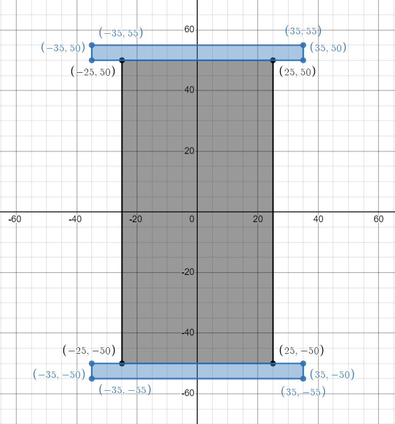
Figure 1: Geometry of the uniaxial compression strength test#
1 Main Steps#
Initialize the model.
Create geometry and mesh
Assign material properties.
Create groups and assign boundary condition.
Set the outputs.
Run
2 Codes#
Warning
Please note that, all the setting in the example is based on the developer’s computer. You may need to change these details based on your own environment.
To start with programming, create a new empty input file or copy it from the existing examples (later add the .of extension). Begin writing the following commands:
2.1 Initialize the model#
Create a new run and clean up the dirty memories in heap, it is not mandatory but strongly recommended.
of.new
Set up the path to save your results. Here the path is set to be “currentPath/result”.
Note
By default, the field results (VTK, VTP) will be saved in “MyResult” folder in the same path with .of file. OpenFDEM kernel will automatically create the folder if it is absent.
of.set.result "result"
Set the interval of logging in the
.logfile. This example uses the default interval 2000 steps..logfile will be useful to help user figure out the running error, and can be used as a tool to debug.
of.log.interval 2000
Set the CPU parallelization to boost your runs.
Warning
In the default example, 15 cores will be used for running. To prevent the heavy burden of your computer, please check your computer to change core number you want to use. To check the configuration of your computer, you can go
- Windows:
Task Manager > Performance > CPU > Cores
- Linux:
lscpu
lscpu | egrep ‘Model name|Socket|Thread|NUMA|CPU(s)’
lscpu -p
The cores will be printed on the console when you start a new run, you can also check the information from OpenFDEM kernel itself.
If nothing is set here, serial computing will be used by default.
of.set.omp 15
2.2 Create the geometry and the mesh#
1. See Figure 1 for the UCS model and create the geometries. This model can be assembeld by three retangulars, the implemented objects OpenFDEM can create include square(rectangular), circle, ellipse, polygon(arbitary shape), Voronoi tessellations, line, etc.
Note
- The following three methods can be used to create the geometry:
xmin x_minvalue xmax x_maxvalue ymin y_minvalue ymax y_maxvalue
x [minvalue, maxvalue] y [minvalue, maxvalue]
[x_minvalue, x_maxvalue, y_minvalue, y_maxvalue] (brackets are indispensable)
This example used three methods to creat a entity. Users may choose any format to create geometris.
of.geometry.square 'rock' xmin -25e-3 xmax 25e-3  ymin -50e-3 ymax 50e-3
of.geometry.square 'up' x [-35e-3, 35e-3] y [50e-3, 55e-3]
of.geometry.square 'down' [-35e-3  35e-3  -55e-3 -50e-3]
2. Define the mesh size geometry and insert cohesive interfaces. You can define a global size on the points in your geometry, it is able to refine some specific parts, assign a smaller mesh size on the point groups you want to refine after your assign the global mesh size.
See also
OpenFDEM is flexible to insert cohesive interfaces only in the objects you want to. For the example at here, the platens are regarded as elastic or rigid in which the breakage will not happen. You can insert cohesive interfaces only in rock physical group to boost the calculation speed to some extent.
of.geometry.mesh.size 'default' 0.8e-3
of.geometry.mesh delaunay
of.mesh.insert 'rock'
2.3 Assign Material Properties#
The material properties of the rock is shown as the table below:
Parameter |
Value |
|---|---|
Continuum Triangular Elements |
|
model |
elastic |
density (\(kg/m^3\)) |
2700 |
E (Pa) |
30e9 |
\(\nu\) |
0.3 |
damp |
1.0 |
Cohesive Material Properties |
|
model |
EM |
tension (Pa) |
1e6 |
cohesion (Pa) |
3e6 |
friction |
0.3 |
GI (\(J/m^2\)) |
10 |
GII (\(J/m^2\)) |
50 |
Contact Material Properties |
|
model |
MC |
friction |
0.3 |
See also
Check element materal, cohesive materal, contact materal to see more materials.
Assign material properties. In this example, elastic material is assigned for the matrix element and Evans_Marathe cohesive law is for CZM, the contact uses Mohr-Coulomb slip by default.
Warning
The tag default is a default keyword implemented in the OpenFDEM kernel, it means the whole physical objects in this model. It will be illegal to use this tag as the name of user-defined physical group.
of.mat.element 'default' elastic den 2700 E 30e9 v 0.3 damp 1.0
of.mat.cohesive 'default' EM ten 1e6 coh 3e6 fric 0.3 GI 10 GII 50
of.mat.contact 'default' MC fric 0.3
2.4 Create Groups and Assign Boundary Conditions#
Group the nodes.
of.group.nodal.from.element 'up' 'up'
of.group.nodal.from.element 'down' 'down'
Assign the nodal boundaries. In this example, top and bottom platens are moving toward to compress the sample, platens are fixed in the x direction and moving with 0.05 m/s in the y direction.
of.boundary.nodal.velocity 'up' x 0.0 y -0.05
of.boundary.nodal.velocity 'down' x 0.0 y 0.05
2.5 Set the Outputs#
1. Set the result writting interval and the field variables you want to dumper. default means the all variables during the calculation will be exported, that will result in huge size for the storage and at the cost of computation efficiency. Control the output interval to a reasonable size could shorten the computation time.
of.history.pv.interval 5000
of.history.pv.field default
of.history.pv.fracture default
2. Timestep can be fixed to 5e-9 in this example to accelerate the calculation in this example, but the default time step is recommended to use. Mass scaling can save you a lot time to some extent, but check the stability of the calculation is always a necessary for the explict integration. User-defined timestep is allowable only if you are rather familiar with the method you are using.
of.timestep fix 5e-9
2.6 Run#
The program will run 500000 steps in total. In other words, it will output 10 files for reference.
of.step 500000
Finalize the model and clear all the temporary memories.
of.finalize
Save the notepad and double click the .of file to run the program.
3 Run the Program#
When you run the program, you can first check the mesh that was created by Gmsh as shown in Figure 2. If the mesh has a good quality, you can close the window to continue run the program.
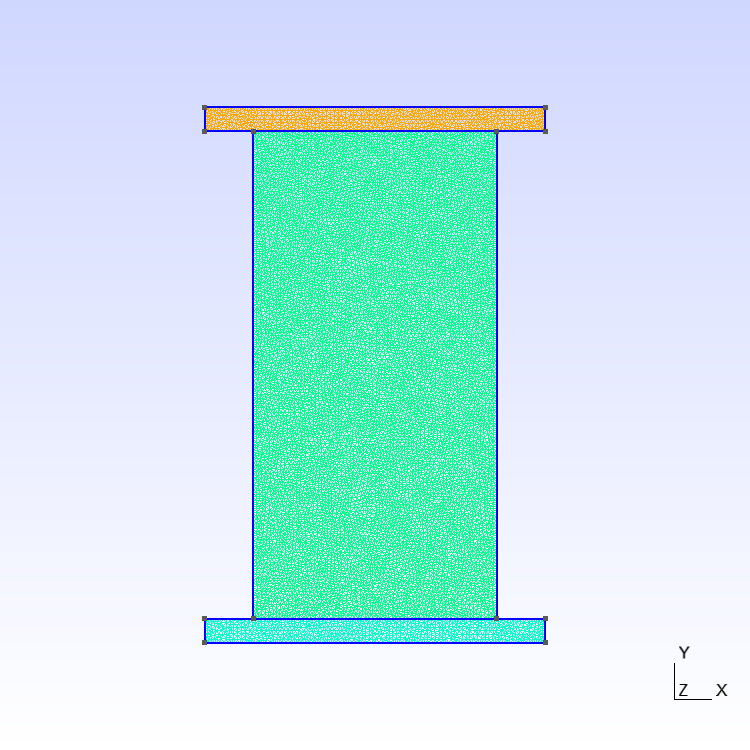
Figure 2: Mesh created by Gmsh#
The mesh is using triangle elements.
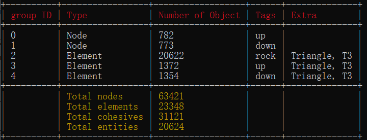
Figure 3: Check the mesh setting from command window#
Material properties you set on step 2.3 will be shown on the screen. You can confirm it while the program just starts to run.
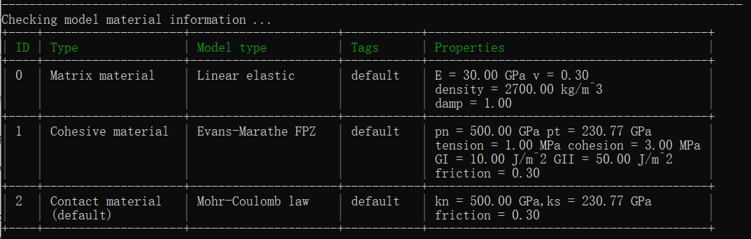
Figure 4: Check the material assignment from command window#
Furthermore, node boundaries are shown at the header of the program.
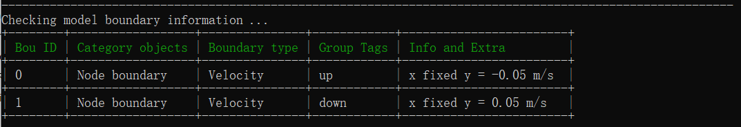
Figure 5: Check the boundary information from command window#
Global timestep is shown here.
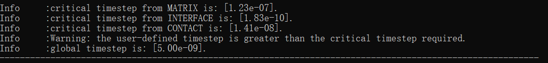
Figure 6: Check the timesteps from command window#
Start to run the program. Results are logged for every 2000 steps.
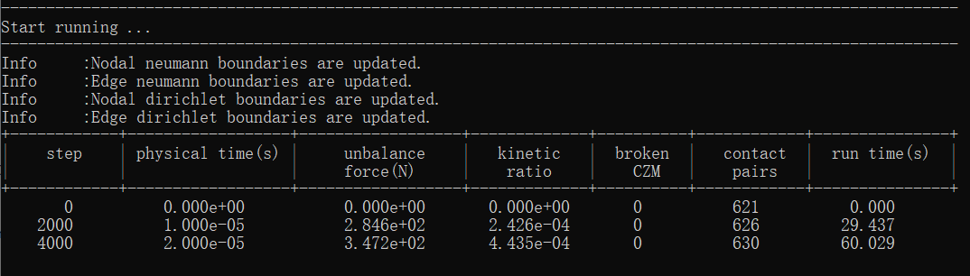
Figure 7: Start to run the program#
4 Results#
Stress YY results.
Figure 8: UCS Stress YY#
Displacement YY results.
Figure 9: UCS Displacement YY#
5 Full Script#
UCS_test.of (click to download from GitHub)
# initialization, this command is to clear the memory in your last run, it is not
# mandatory but strongly recommend.
of.new

# Set the path folder of your output results, //result// in the same path of your input
# file will be created by default
of.set.result "result"

# Set the interval of logging in the log file, 2000 is by default, not mandatory
of.log.interval 2000

# Set the number of cores you want to use, the parallization will be automatically turned
# on when you use the following command, otherwise the serilization will be used by
# default
of.set.omp 15

###################################### create mesh ######################################
# Create a box having the group tag 'rock', the box is defined by the minimum and maximum
# coordinations of each edge.
of.geometry.square 'rock' xmin -25e-3 xmax 25e-3  ymin -50e-3 ymax 50e-3
# Create the upper platen
of.geometry.square 'up' x [-35e-3, 35e-3] y [50e-3, 55e-3]
# Create the down platen.
of.geometry.square 'down' [-35e-3  35e-3  -55e-3 -50e-3]
# Assign the mesh size
of.geometry.mesh.size 'default' 0.8e-3
# to execute the kernel for meshing, the kernel will automatically export a mesh file
# named "mess.msh" in the input folder. Users can of.import "mesh.msh" to run the model
# again without recreating the mesh
of.geometry.mesh delaunay

# Insert the cohesive elements.
of.mesh.insert 'rock'

################################# assign material parameters ############################
# Assign material for matrix.
of.mat.element 'default' elastic den 2700 E 30e9 v 0.3 damp 1.0
# Assign material for CZM
of.mat.cohesive 'default' EM ten 1e6 coh 3e6 fric 0.3 GI 10 GII 50
# Assign materials for contacts
of.mat.contact 'default' MC fric 0.3

##################################### create groups #####################################
# OpenFDEM can manually group the nodes, elements, cohesive elements and edges by using
# the region of box, circle and plane.
of.group.nodal.from.element 'up' 'up'
of.group.nodal.from.element 'down' 'down'

################################### assign boundaries ###################################
# boundaries can be assigned after you define the groups
of.boundary.nodal.velocity 'up' x 0.0 y -0.05
of.boundary.nodal.velocity 'down' x 0.0 y 0.05

####################################### set output ######################################
# Set the interval of writing ParaView results.
of.history.pv.interval 5000
# Output all results by default.
of.history.pv.field default
of.history.pv.fracture default

##################################### execute model #####################################
# Manually set the timestep to overwirte the default timestep suggested by the program.
# It is not recommended to manually increase the size of timesteps unless the user has
# enough understanding of the calculation process.
of.timestep fix 5e-9
# to excuate the model
of.step 500000
# finalize the model and clear the memory
of.finalize