Thermal flux transportation in a bar#
In this tutorial, thermal module will be review. Contact thermal transition from FEM (left) part to FDEM (right) part will be modeled by triangular elements (left) and quadrilateral elements (right).
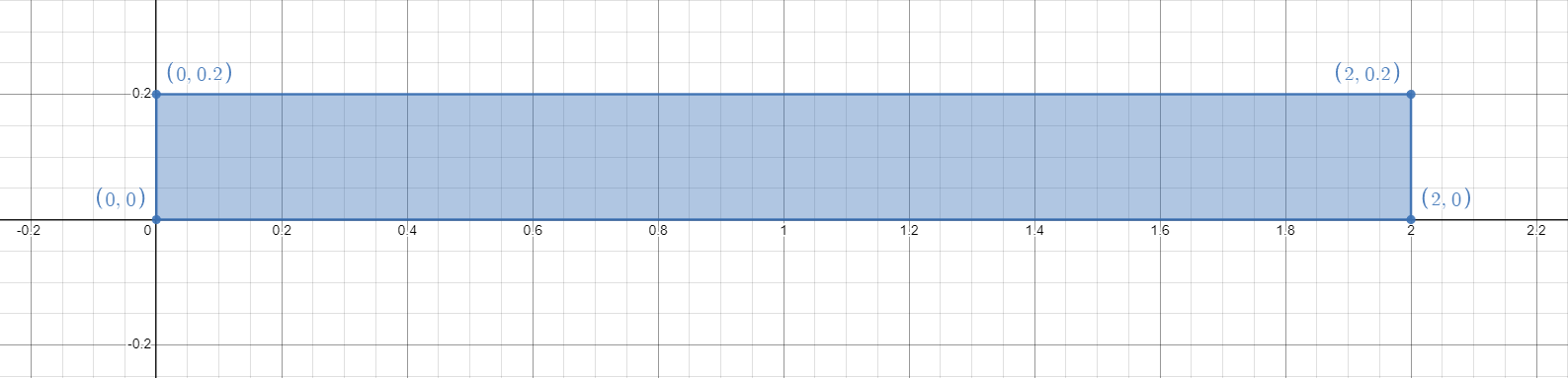
Figure 1: Geometry of the uniaxial compression strength test#
1 Main Steps#
Initialize the model.
Create the geometry and the mesh
Assign material properties.
Create the group and assign boundary conditions.
Set the outputs.
2 Codes#
Warning
Please note that, all the setting in the example is based on the developer’s computer. You may need to change these details based on your own environment.
To start with programming, create a new empty input file or copy it from the existing examples (later add the .of extension). Begin writing the following commands:
2.1 Initialize the model#
Create a new run and clean up the old memories.
of.new
Set up the folder name to save your results. Here the folder name is set to be “result”.
of.set.result "result"
Set the number of cores to be used for running this model.
Warning
In the default example, 15 cores will be used for running. To prevent the heavy burden of your computer, please check your computer to change core number you want to use. To check the configuration of your computer, you can go
- Windows:
Task Manager > Performance > CPU > Cores
- Linux:
lscpu
lscpu | egrep ‘Model name|Socket|Thread|NUMA|CPU(s)’
lscpu -p
The cores will be printed on the console when you start a new run, you can also check the information from OpenFDEM kernel itself.
If nothing is set here, serial computing will be used by default.
of.set.omp 15
2.2 Create the geometry and the mesh#
See Figure 1 for the thermal conduction setup and draw the corresponding geometry.
of.geometry.square 'barleft' xmin 0 xmax 1.0 ymin  0 ymax 0.2
of.geometry.square 'barright' xmin 1.0 xmax 2.0 ymin  0 ymax 0.2
Set the mesh size of the geometry.
of.geometry.mesh.size 'default' 0.05
Set the quadrangle elements
of.geometry.recombine 'barright'
Create the mesh.
of.geometry.mesh delaunay
2.3 Assign Material and Thermal Properties#
Parameter |
Value |
|---|---|
Continuum Triangular Elements |
|
model |
elastic |
density (\(kg/m^3\)) |
2700 |
E (Pa) |
5e8 |
\(\nu\) |
0.2 |
Cohesive Material Properties |
|
model |
EM |
tension (Pa) |
1e6 |
cohesion (Pa) |
3e6 |
friction |
0.3 |
GI (\(J/m^2\)) |
10 |
GII (\(J/m^2\)) |
50 |
heat_exchange (\(^\circ C\)) |
20 |
Contact Material Properties |
|
model |
MC |
friction |
0.3 |
conductivity |
200 |
Thermal Properties |
|
conductivity |
160 |
spec-heat |
0.2 |
expansion |
1e-6 |
Set the material properties.
of.mat.element 'default' elastic density 2700 E 5e8 v 0.2
of.mat.cohesive 'default' EM ten 1e6 coh 3e6 fric 0.3 GI 10 GII 50 heat_exchage 20
of.mat.contact 'default' MC fric 0.3 conductivity 200
Set the thermal properties.
of.mat.thermal 'default' conductivity 160 spec-heat 0.2 expansion 1e-6
2.4 Create Groups and Assign Boundary Conditions#
Create boundary groups on object:node, the range method is on the plane, all the nodes on the plane will be added into the specific groups. The plane is defined by the start point and end point.
of.group.nodal 'left' range plane.on x0 0.0 y0 0.0 x1 0.0 y1 0.2
of.group.nodal 'right' range plane.on  x0 2.0 y0  0.0 x1 2.0 y1 0.2
of.group.nodal 'up' range plane.on  x0 0.0 y0  0.2 x1 2.0 y1 0.2
of.group.nodal 'down' range plane.on x0 0.0 y0  0.0 x1 2.0 y1 0.0
Assign the thermal properties to the model. In this model, the temperature of the left of the example is 50 degree Celsius. The temperature of the right of the example is 0 degree Celsius. Heat will be conducted in this model from left to right.
of.boundary.thermal.temperature 'left' T 50
of.boundary.thermal.temperature 'right' T 0.0
Assign the nodal boundaries. In this model, top, bottom and right boundaries are fixed in both x and y directions.
of.boundary.nodal.velocity 'right' x 0.0 y 0.0
of.boundary.nodal.velocity 'up' x 0.0 y 0.0
of.boundary.nodal.velocity 'down' x 0.0 y 0.0
2.5 Set the Outputs#
Set the output interval to be every 500 steps and output all fields variables and fracture variables. Control the output interval to a reasonable size could shorten the computation time but get a good understanding of the model.
of.history.pv.interval 500
of.history.pv.field default
of.history.pv.fracture default
Timestep of thermal calculation can be fixed to 5e-5 in this example.
of.thermal.timestep 5e-5
The program will run 15000 steps in total. In other words, it will output 10 files for reference.
of.step 15000
Finalize the model and clear all the temporary memories.
of.finalize
Save the notepad and double click the .of file to run the program.
3 Run the Program#
When you run the program, you can first check the mesh that was created by Gmsh as shown in Figure 2. If the mesh has a good quality, you can close the window to continue run the program.
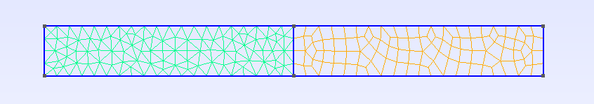
Figure 2: Mesh created by Gmsh#
The thermal module is ON in this model.
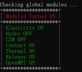
Figure 3: Global modules#
Material properties you set on step 2.3 will be shown on the screen. You can confirm it while the program just starts to run.
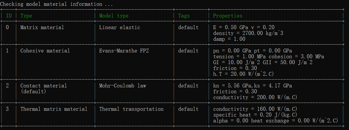
Figure 4: Check the material assignment from command window#
Furthermore, node boundaries are shown at the header of the program.
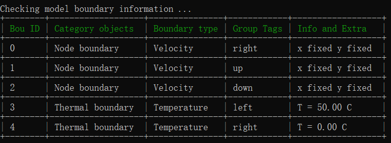
Figure 5: Check the boundary information from command window#
4 Results#
Thermal flow
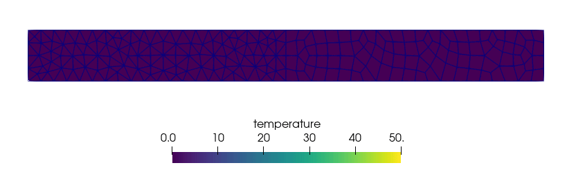
Figure 6: Thermal Flow#
5 Full Script#
Thermal_Flux.of (click to download from GitHub)
# initialization, this command is to clear the memory in your last run, it is not
# mandatory but strongly recommend.
of.new

# Set the path folder of your output results, //result// in the same path of your input
# file will be created by default
of.set.result "result"

# Set the number of cores you want to use, the parallization will be automatically
# turned on when you use the following command, otherwise the serilization will be used
# by default
of.set.omp 15

#################################### create mesh ######################################
of.geometry.square 'barleft' xmin 0 xmax 1.0 ymin  0 ymax 0.2
of.geometry.square 'barright' xmin 1.0 xmax 2.0 ymin  0 ymax 0.2
of.geometry.mesh.size 'default' 0.05
of.geometry.recombine 'barright'
of.geometry.mesh delaunay

############################### assign material parameters ############################
# assign material for matrix
of.mat.element 'default' elastic density 2700 E 5e8 v 0.2
# heat exchange in cohesive elements
of.mat.cohesive 'default' EM ten 1e6 coh 3e6 fric 0.3 GI 10 GII 50 heat_exchage 20
# conductivity of thermal in contacts
of.mat.contact 'default' MC fric 0.3 conductivity 200

#set thermal matrix parameter
of.mat.thermal 'default' conductivity 160 spec-heat 0.2 expansion 1e-6

##################################### create groups ##################################
of.group.nodal 'left' range plane.on x0 0.0 y0 0.0 x1 0.0 y1 0.2
of.group.nodal 'right' range plane.on  x0 2.0 y0  0.0 x1 2.0 y1 0.2
of.group.nodal 'up' range plane.on  x0 0.0 y0  0.2 x1 2.0 y1 0.2
of.group.nodal 'down' range plane.on x0 0.0 y0  0.0 x1 2.0 y1 0.0

################################### assign boundaries ################################
# boundaries can be assigned after you define the groups
of.boundary.thermal.temperature 'left' T 50
of.boundary.thermal.temperature 'right' T 0.0
of.boundary.nodal.velocity 'right' x 0.0 y 0.0
of.boundary.nodal.velocity 'up' x 0.0 y 0.0
of.boundary.nodal.velocity 'down' x 0.0 y 0.0

################################### set output #######################################
# Set the interval of writing ParaView results.
of.history.pv.interval 500
of.history.pv.field default
of.history.pv.fracture default

################################## execute model #####################################
# set the timestep for thermal module
of.thermal.timestep 5e-5
# to excuate the model
of.step 15000
# finalize the model and clear the memory
of.finalize